 en
en  Español
 عربى
عربىHow do you correctly connect Air Conditioning Copper Pipe Connectors?
To correctly connect air conditioning copper pipe connectors, you must cut the pipe cleanly, deburr and ream the end, insert it fully into the connector, and either flare, braze, or tighten the fitting to the manufacturer's specified torque — then pressure-test the joint before charging the system with refrigerant. Skipping any of these steps is the leading cause of refrigerant leaks, which reduce system efficiency, increase operating costs, and can violate environmental regulations. The sections below walk through every stage in detail so each joint is made correctly the first time.
Content
- 1 Understanding What Air Conditioning Copper Pipe Connectors Do
- 2 Tools and Materials to Prepare Before Starting
- 3 Step-by-Step Guide to Cutting and Preparing the Copper Pipe
- 4 How to Make a Correct Flare Connection
- 5 How to Make a Correct Brazed (Soldered) Connection
- 6 Connecting Push-Fit and Compression-Type Connectors
- 7 Comparison of Connector Types and When to Use Each
- 8 Pressure Testing and Leak Checking After Connection
- 9 Common Connection Mistakes and How to Avoid Them
- 10 Insulating and Protecting Completed Connections
- 11 Maintenance and Periodic Inspection of Installed Connectors
Understanding What Air Conditioning Copper Pipe Connectors Do
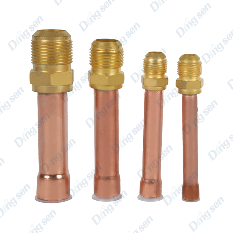
Air conditioning copper pipe connectors are precision fittings — manufactured from brass using CNC turning and seal-tested before shipment — whose sole job is to form a leak-proof path for refrigerant between components. A split-system air conditioner operating at a typical low-side pressure of 0.5–0.9 MPa and a high-side pressure of 1.5–2.5 MPa (values vary by refrigerant type) puts every joint under constant mechanical and thermal stress. Connectors must therefore seal against both pressure and the solvent action of refrigerant oils.
These fittings cover a broad range of joining needs:
- Connecting copper pipes of the same diameter in a straight run (couplings and unions)
- Joining pipes of different diameters where line sets transition between indoor and outdoor units (reducers)
- Changing direction in tight equipment rooms or wall penetrations (elbows — 45° and 90°)
- Splitting refrigerant flow to multiple indoor units in multi-split systems (tees and distributors)
- Enabling disconnection for servicing without destroying the pipe run (flare unions and SAE flare adapters)
The brass alloy used in quality connectors — typically CuZn39Pb2 or equivalent — provides the corrosion resistance needed to survive decades of contact with refrigerants such as R-22, R-410A, R-32, and R-134a, as well as their associated lubricating oils.
Tools and Materials to Prepare Before Starting
Arriving at the job with the correct tools prevents improvisation that damages connectors and pipe ends. The following equipment is required for a professional installation:
- Pipe cutter (ratchet-type or rotary) — produces a square, burr-free cut without deforming the tube wall. Hacksaw cutting is not acceptable for refrigeration-grade work.
- Reamer and deburring tool — removes the internal burr left by the cutter; a burr as small as 0.5 mm can restrict flow and cause turbulence that erodes the connector bore over time.
- Flaring tool and cone — required for all flare-type connections; a proper flare produces a smooth, crack-free 45° cone that mates precisely with the connector seat.
- Torque wrench (10–80 N·m range) — essential for tightening flare nuts to the specified value without over-tightening, which splits the flare.
- Pipe bender — for forming smooth bends in the copper tube before fitting connection, avoiding kinks that restrict flow.
- Nitrogen cylinder and regulator — for purging and pressure-testing after connection; dry nitrogen at 1.5× the maximum operating pressure is the standard test medium.
- Electronic leak detector or soap solution — for confirming joint integrity before system commissioning.
- Oxyacetylene or MAP gas torch with appropriate tip — if brazing solder-type fittings; required for copper-to-brass joints.
- Refrigerant-compatible thread sealant or PTFE tape — for NPT-threaded connectors only; never apply to flare seats.
Step-by-Step Guide to Cutting and Preparing the Copper Pipe
Correct pipe preparation is the foundation of a leak-free joint. Poor preparation accounts for a significant proportion of field callbacks in air conditioning installation.
Measuring and Marking
Measure the required pipe length allowing for the insertion depth of the connector — typically 10–25 mm depending on connector size. Mark the cut point clearly with a felt pen. Avoid scribing with a sharp tool, which can crack work-hardened copper.
Cutting the Pipe Squarely
Position the rotary cutter on the mark and tighten the blade lightly against the tube. Rotate the cutter around the tube, advancing the blade by a quarter turn per revolution. Overtightening the blade in one pass compresses and work-hardens the tube end, making flaring difficult. A correctly cut end is perpendicular to the tube axis — any angular deviation greater than 1° compromises the flare seat contact.
Reaming and Deburring
Insert the reamer into the cut end and rotate it to remove the internal burr completely. After reaming, point the pipe end downward and tap it gently to dislodge copper shavings before they enter the system. Even a single metal chip lodged in an expansion valve can cause immediate compressor damage.
Cleaning the Pipe Surface
Wipe the outside of the pipe end with a clean, dry cloth to remove surface oxidation, cutting oil residue, and dust. For brazed connections, lightly abrade the pipe end with fine emery cloth over a length equal to the socket depth of the fitting, then wipe again. Do not use chlorinated solvents, which leave residues that attack refrigerant seals.
How to Make a Correct Flare Connection
Flare connections are the most common type used in residential and light-commercial split-system air conditioning because they are fully reversible — the system can be disconnected for servicing and reconnected without replacing the pipe. A correctly formed flare requires attention at every stage.
Sliding on the Flare Nut First
Before forming the flare, slide the flare nut onto the pipe with the threaded end facing away from the pipe end. This is one of the most common mistakes made by inexperienced technicians — discovering the nut has been forgotten after the flare is already formed means cutting the pipe and starting again.
Setting the Correct Pipe Protrusion
Clamp the pipe in the flaring block with the pipe end protruding above the block face by the amount specified for the pipe outside diameter. Typical protrusion values are:
| Pipe OD (mm) | Protrusion Above Block (mm) | Flare OD Target (mm) | Flare Nut Torque (N·m) |
|---|---|---|---|
| 6.35 (1/4") | 1.0 – 1.5 | 9.1 | 14 – 18 |
| 9.52 (3/8") | 1.0 – 1.5 | 13.2 | 33 – 42 |
| 12.70 (1/2") | 1.5 – 2.0 | 16.6 | 49 – 61 |
| 15.88 (5/8") | 1.5 – 2.0 | 19.7 | 68 – 82 |
Forming the Flare
Advance the flaring cone with steady, even pressure — do not rush the final stages. The finished flare must be smooth, concentric, and free of cracks, splits, or wrinkles. A cracked flare will leak immediately; a wrinkled flare may pass a static pressure test but fail under thermal cycling in service. Applying a small amount of refrigerant oil to the cone before flaring reduces galling and produces a shinier, smoother seating surface.
Tightening the Flare Nut to Torque
Hand-tighten the flare nut onto the connector body until resistance is felt, then use two wrenches — one to hold the connector body stationary and one to turn the nut — to avoid twisting stress on the pipe. Apply the torque wrench to reach the value in the table above. Never use the pipe itself as a lever to prevent the connector from rotating; this work-hardens and cracks the copper near the flare.
How to Make a Correct Brazed (Soldered) Connection
Brazed connections using silver-alloy filler are used for permanent joints in commercial systems, larger-diameter pipes (typically above 28 mm OD), and any joint subject to high vibration. When done correctly, the brazed joint is as strong as the parent pipe material and will outlast the equipment it serves.
Nitrogen Purging During Brazing
Before igniting the torch, connect a dry nitrogen feed to the pipe system and establish a flow of 0.5–1.0 L/min through the pipe being brazed. Nitrogen displaces oxygen inside the tube, preventing the formation of copper oxide scale (cuprous oxide) on the bore surface. Oxide scale flakes off during commissioning, travels with the refrigerant, and can block the expansion device within hours. Nitrogen purging during brazing is an industry-standard requirement, not an optional step.
Applying Flux and Heating the Joint
Apply a thin, even coat of brazing flux to the pipe end and the socket interior of the connector. Insert the pipe fully into the connector socket. Direct the torch flame at the connector body and the base of the socket, not the filler rod or the pipe end directly. Heat the joint evenly by moving the flame in small circles until the flux becomes clear and the copper glows a dull red — approximately 700–800 °C for silver-alloy filler brazing.
Feeding the Filler Rod
Remove the torch briefly and touch the silver-alloy filler rod to the gap between pipe and connector at the socket mouth. If the joint is at the correct temperature, the filler will be drawn into the socket by capillary action and fill the annular gap completely without the need to push or force it. A correctly brazed joint uses only the amount of filler needed to fill the socket — excess filler forming a bead at the socket mouth indicates too much material or overheating.
Cooling and Cleaning
Allow the joint to cool naturally in still air until it is no longer glowing. Do not quench with water — rapid cooling can introduce thermal stress cracks in the connector body. Once cooled to below 50 °C, wipe off flux residue with a damp cloth; flux left on the joint is mildly corrosive and will attack the copper surface over time.
Connecting Push-Fit and Compression-Type Connectors
Push-fit and compression connectors fitted with refrigerant-resistant sealing rings offer a flameless alternative to brazing for smaller pipe sizes, making them suitable for use in occupied spaces where a naked flame is not permitted. The sealing ring material — typically EPDM or NBR — is selected to be compatible with both the refrigerant and its lubricating oil.
Insertion Depth and Marking
Before inserting the pipe, mark the required insertion depth on the pipe exterior using a felt pen. This mark should appear at the connector body face after full insertion, confirming the pipe has reached the sealing zone. A pipe inserted only partway seats against the seal unevenly and will leak under pressure.
Pipe End Condition Requirements
Push-fit connectors are especially sensitive to pipe end condition. The outer diameter must be within ±0.1 mm of the nominal value, the end must be perfectly square, and there must be no burrs, scratches, or score marks on the outer surface in the sealing zone — typically the first 25–40 mm from the pipe end. Even a shallow longitudinal scratch from the cutter blade can create a leak path past the sealing ring.
Completing the Connection
Apply a thin film of clean refrigerant oil (compatible with the system's lubricant) to the pipe end in the sealing zone — this reduces insertion force and prevents the sealing ring from being rolled or cut during assembly. Push the pipe firmly into the connector until the depth mark aligns with the connector face; you should feel a distinct click or resistance increase as the pipe locks into position. Pull back lightly to confirm the pipe is retained before releasing.
Comparison of Connector Types and When to Use Each
Selecting the correct connector type for the application avoids both over-engineering (which wastes time and cost) and under-engineering (which creates reliability problems). The table below summarizes the main connector categories, their key characteristics, and their recommended applications.
| Connector Type | Joint Method | Reversible? | Typical Pipe OD | Best Application |
|---|---|---|---|---|
| SAE Flare Union | 45° flare + torqued nut | Yes | 6.35 – 19.05 mm | Residential split-system line sets; service connections |
| Brazed Socket Coupling | Silver-alloy capillary brazing | No | 6.35 – 54 mm | Commercial and industrial permanent piping |
| Push-Fit Connector | Sealing ring + grab ring | With tool | 6.35 – 22 mm | Flame-free zones; renovation work in occupied buildings |
| Compression Fitting | Ferrule compressed by nut | Limited | 6.35 – 28 mm | Equipment connections; field repair splicing |
| Flare Reducer | Dual-diameter flare seats | Yes | Mixed sizes | Connecting new units to existing line sets of different diameter |
Pressure Testing and Leak Checking After Connection
No refrigeration system should be charged with refrigerant before the pipe work has been pressure-tested and confirmed leak-free. A pressure test takes 15–30 minutes but can prevent hours of refrigerant recovery, leak tracing, and component replacement later.
Nitrogen Pressure Test Procedure
- Isolate the system from the atmosphere by closing all service valves and blanking open ports.
- Connect a dry nitrogen cylinder with a regulator set to the test pressure — typically 1.5 MPa for R-410A systems and 2.0 MPa for R-32 systems (always verify against the equipment manufacturer's data).
- Pressurize the system slowly, pausing at 0.5 MPa for a preliminary visual inspection before increasing to full test pressure.
- Hold at test pressure for a minimum of 24 hours for new installations, or 1 hour for repair work on individual joints, monitoring the test gauge for any pressure drop.
- Apply an approved leak-detection solution to every joint and examine for bubble formation; an electronic halogen leak detector can also be used for faster surveying.
- Any pressure drop greater than 0.02 MPa over 1 hour (corrected for temperature change) indicates a leak that must be located and rectified before proceeding.
Vacuum Test Before Refrigerant Charge
After passing the pressure test, the system must be evacuated to remove moisture and non-condensable gases. A two-stage vacuum pump should achieve a final vacuum of 500 microns (0.067 kPa) or lower. Hold the vacuum for at least 30 minutes after isolating the pump; any rise in pressure indicates either residual moisture or a leak that the nitrogen test may have missed due to its direction-dependent sensitivity.
Common Connection Mistakes and How to Avoid Them
Even experienced technicians occasionally make errors under time pressure. The following are the most frequently encountered connection faults, their consequences, and how to prevent them:
- Flare nut forgotten before flaring — the flare must be cut off and reformed after sliding on the nut. Prevention: follow a checklist; confirm the nut is on the pipe before clamping.
- Over-tightened flare nut — splits the flare rim, creating a hairline crack that leaks. Torque values are in the fitting manufacturer's data sheet; always use a torque wrench rather than estimating by feel.
- Copper swarf left in the pipe — travel to the expansion valve or compressor and cause mechanical damage within hours. Always point the cut end downward after reaming and tap before assembly.
- Brazing without nitrogen purge — oxide scale forms inside the pipe, breaks off during operation, and blocks the expansion device. Nitrogen purging is mandatory.
- Mixing incompatible refrigerants and sealing ring materials — R-32, for example, requires sealing rings rated for its higher operating pressure and different solvent characteristics compared with R-22. Always match the connector's sealing ring specification to the system's refrigerant.
- Applying PTFE tape to flare seats — PTFE tape is for tapered thread joints only. Applied to a flare seat, it prevents metal-to-metal contact and does not improve the seal; it creates an uneven seating surface that causes leaks.
- Pipe not fully inserted in push-fit connector — the sealing ring does not engage correctly at partial insertion. Mark the pipe with the required insertion depth and confirm the mark reaches the connector face.
Insulating and Protecting Completed Connections
Once joints are confirmed leak-free and the system is charged, the copper pipe and connectors must be insulated and protected from the environment. This is not a cosmetic step — it directly affects energy efficiency and connector longevity.
Thermal Insulation
Closed-cell foam insulation (typically 9–13 mm wall thickness for suction lines) is applied to all low-side refrigerant pipes to prevent condensation on the pipe surface and minimize heat gain. An uninsulated suction line in a warm, humid environment can gain enough heat to reduce system COP by 5–15% depending on line length. Insulation must extend over the connector body, not stop at the fitting edge.
UV and Mechanical Protection for Outdoor Runs
Exposed outdoor pipe runs should be encased in UV-resistant trunking or wrapped with an aluminum-foil-faced tape over the insulation. Direct sunlight degrades foam insulation within 2–3 years of unprotected outdoor exposure, removing the thermal and condensation protection from the connector area. At wall penetrations, use a suitable grommet or pipe sleeve to prevent the sharp masonry edge from cutting the insulation and exposing the copper.
Vibration Isolation
Compressor vibration transmitted through the pipe work fatigues flare joints over time. Where the pipe connects to the outdoor unit, provide at least 300–500 mm of unsupported flexible pipe run before the first rigid support clip to absorb vibration rather than transmitting it directly to the connector. Rigid clips attached directly to the unit casing are a common cause of work-hardening and cracking of copper pipe near flare connections.
Maintenance and Periodic Inspection of Installed Connectors
Even correctly installed connectors benefit from periodic inspection, particularly in commercial systems running year-round. A proactive maintenance schedule catches developing issues before they become refrigerant losses.
Recommended inspection items during routine system servicing (annually or per the equipment manufacturer's schedule):
- Inspect all accessible flare unions and compression fittings for oil staining around the nut — an oily residue at a joint indicates a slow refrigerant/oil leak that has not yet produced a detectable pressure loss.
- Check that all insulation on connector bodies is intact and dry; compressed or water-saturated insulation should be replaced.
- Re-torque flare nuts on any system that has experienced significant thermal cycling (temperature swings greater than 30 °C across the joint) — thermal expansion and contraction can gradually relax the nut preload.
- Inspect outdoor connectors for signs of external corrosion, particularly in coastal or industrial environments where airborne chlorides or sulfur compounds accelerate brass corrosion.
- Use a calibrated electronic leak detector at all joints annually; detectors sensitive to 5 g/year refrigerant leak rate will identify developing leaks well before they affect system performance.
-

Air conditioning copper pipe female-male connector are core fittings for connect...
-

Air conditioning copper pipe duoble connector are core fittings for connecting t...
-

The air conditioning copper tube reamer is a specialized tool for connecting cop...
-

Air conditioning copper pipe reducing double joints are core fittings for connec...
-

Air conditioning plastic nuts are lightweight seals for connecting copper pipes ...
-

Air conditioning reducing nuts are sealed connectors for connecting copper pipes...
Contact Us
-

No. 109 Jiefang Road, Diankou Town, Zhuji City, Shaoxing, Zhejiang Province
-

+86-13867581196
-

Copyright © shaoxing DingSen Refrigeration Technology Co Ltd. All Rights Reserved
OEM Refrigeration Parts Manufacturer Custom Automotive AC Parts Factory