
 en
en  Español
 عربى
عربى
What Is Intrinsic Safety? Definition, Limits, and Hazardous Area Design
A technician clamps a leak detector onto a chiller charged with R290 propane. The tool runs on a 9 V battery, sits about 20 mm from a joint that has just started to weep, and nobody looks twice at the electronics inside it. Intrinsic safety exists because that second look is what prevents an explosion. The term describes a protection technique that keeps the electrical and thermal energy inside a circuit below the level that can ignite the surrounding flammable atmosphere, in normal operation and under a defined number of fault conditions.
The definition sounds modest, but it reshapes everything downstream. Because protection comes from limiting energy rather than from containing an explosion, it covers the whole loop, including the wires that run back to the control cabinet. It also means the design can be calculated and certified before anything reaches the site.
Content
- 1 The Formal Definition and the Three Limits
- 2 What an Intrinsically Safe Circuit Actually Contains
- 3 Intrinsic Safety Compared With Other Protection Methods
- 4 Where Intrinsic Safety Shows Up in Refrigeration and Air Conditioning
- 5 How Much Energy Are We Really Talking About
- 6 Two Comparisons That Decide a Design
The Formal Definition and the Three Limits
The formal wording comes from IEC 60079-11, the standard behind the Ex i marking, and it is repeated in the European ATEX Directive 2014/34/EU and in the IECEx scheme. A device qualifies as intrinsically safe when the energy it can release is limited so that ignition cannot occur in normal operation or under defined fault conditions.
Three quantities are controlled together, and any one of them can start a fire:
- Voltage, because a spark needs enough potential to break down the gap between conductors.
- Current, because the energy in a break spark rises with current and with circuit inductance.
- Power and surface temperature, because a hot surface can ignite a gas without any spark at all.
The limits are not chosen by the designer. Every certified field device is published with entity parameters: maximum input voltage Ui, input current Ii, input power Pi, and internal capacitance and inductance Ci and Li. The barrier or isolator at the other end of the cable publishes matching output values Uo, Io and Po, while the cable adds capacitance and inductance for every metre of its length. A loop is compliant only when each pair lines up with margin to spare.
The rules are deliberately conservative. Spark ignition curves are applied with a safety factor, commonly 1.5, so the certified limit already sits below the energy that ignited the gas in laboratory testing. For group IIC gases such as hydrogen and acetylene, a typical circuit stays under 30 V, near 100 mA and a fraction of a watt, while a comparable design for methane can carry noticeably more. T6 caps surface temperature at 85 degrees Celsius and T4 at 135 degrees Celsius, well below the auto-ignition temperature of the gases they cover.
What an Intrinsically Safe Circuit Actually Contains
Three parts make up a working installation, and all three have to match on paper before any of them is ordered.
The field device in the classified area
This is the instrument, switch, coil or sensor exposed to the atmosphere, and its marking shows the fault tolerance it carries. Ex ia stays safe with two faults and is permitted in Zone 0, where a flammable atmosphere is present continuously or for long periods. Ex ib covers Zone 1 with one fault, and Ex ic covers Zone 2, where an atmosphere is unlikely and short lived.
The barrier or isolator in the safe area
The associated apparatus limits the energy that reaches the field. A zener barrier uses shunt diodes, a fuse and a resistor, and needs a dedicated safety earth measured at under 1 ohm. A galvanic isolator works through transformers or optical coupling and needs no safety earth, which is why it is often chosen where earthing is difficult to prove and maintain.
Simple apparatus and passive contacts
Not every component needs a certificate of its own. IEC 60079-11 allows simple apparatus, defined as a device that neither generates nor stores more than 1.2 V, 0.1 A, 20 microjoules or 25 mW. Passive switches, thermocouples, terminal boxes and simple pressure switch contacts qualify as long as the surrounding loop is already energy limited. This is where a refrigeration pressure controller earns its place in a design: its contacts share a housing with a process connection that may sit in a classified area, and because those contacts only ever carry a limited loop current, the enclosure does not have to become a flameproof box.
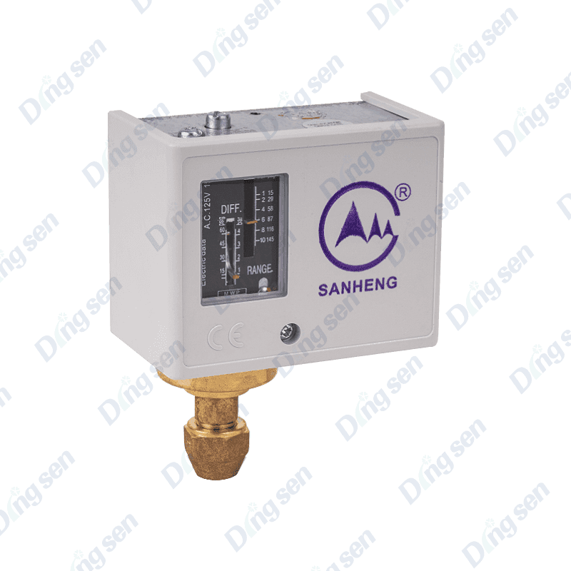 Refrigeration pressure controllerThe refrigeration pressure controller features a rectangular box with a white, corrosion-resistant plastic housing. Mechanical pointer pressure gauges on both sides of...View Product →
The cable between them
Cable is a component, not an accessory. Intrinsically safe wiring is normally blue sheathed and segregated from non-IS circuits by 50 mm or by an earthed metallic partition, and its capacitance and inductance per metre are entered into the loop calculation.
Intrinsic Safety Compared With Other Protection Methods
Hazardous area protection is a family of techniques rather than a single answer. The table below puts intrinsic safety beside the methods it is most often weighed against.
| Method and marking | How ignition is prevented | Typical zone | Live maintenance | Relative installed cost |
|---|---|---|---|---|
| Intrinsic safety, Ex ia, Ex ib, Ex ic | Energy in the loop is limited by a barrier or isolator, so no spark and no hot surface can ignite the atmosphere | Zone 0 with ia, Zone 1 with ib, Zone 2 with ic | Yes, under a permit and a written procedure | Medium to high |
| Flameproof, Ex d | The enclosure contains an internal explosion and cools the escaping gas below its ignition temperature | Zone 1 and Zone 2 | No, the circuit must be de-energised | Medium |
| Increased safety, Ex e | Clearances, creepage distances and terminations are designed so that sparks and hot surfaces do not occur | Zone 1 and Zone 2 | No | Low to medium |
| Non incendive, Ex n | The circuit cannot ignite the atmosphere in normal operation only | Zone 2 | Limited | Low |
| Pressurisation, Ex p | Air or inert gas pressure keeps the flammable atmosphere out of the enclosure | Zone 1 and Zone 2 | Limited | High |
Where Intrinsic Safety Shows Up in Refrigeration and Air Conditioning
Flammable refrigerants moved the subject from the chemical plant into the chiller room. R290 and R600a sit in group A3, while R32 and R454B sit in A2L, which means the space around an appliance can be classified where a leak is credible. Once a zone exists, the electrical parts attached to that circuit have to be protected accordingly.
Electrical components inside a flammable refrigerant envelope
A solenoid coil that opens under load produces exactly the inductive break spark that entity parameters for inductance were written for, and a pressure switch opening on a fault does the same. Coils, switches and sensors are therefore chosen with the zone in mind, and a coil rating is checked separately from the valve body. A refrigeration solenoid valve such as the EVR series is a familiar example of a body selected for pressure, refrigerant compatibility and sealing, one that becomes suitable for a classified area only when paired with a correctly rated coil and circuit.
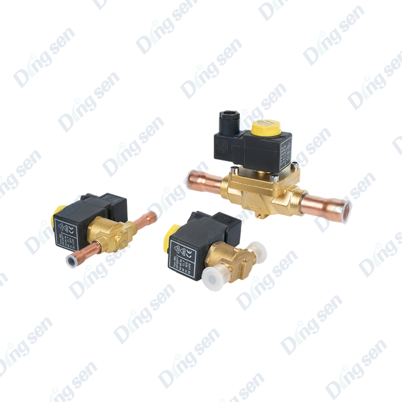 EVR solenoid valveEVR solenoid valves are key components in refrigeration and air conditioning, controlling the flow of refrigerant through electromagnetic induction. Available in direc...View Product →
The site keeps a short technical note on how EVR type solenoid valves in refrigeration circuits behave in service, which is a useful starting point for that check.
Thermal energy and hot work near an open circuit
Intrinsic safety covers thermal energy as well as electrical energy, and service work is where that distinction bites. Brazing a joint on a circuit that has just been opened means a flame, a hot tube and refrigerant that may still be present in the line. The practical controls are a nitrogen purge, a gas check before the torch is lit, and a torch whose flame can be held at the size the joint actually needs rather than at the largest setting available.
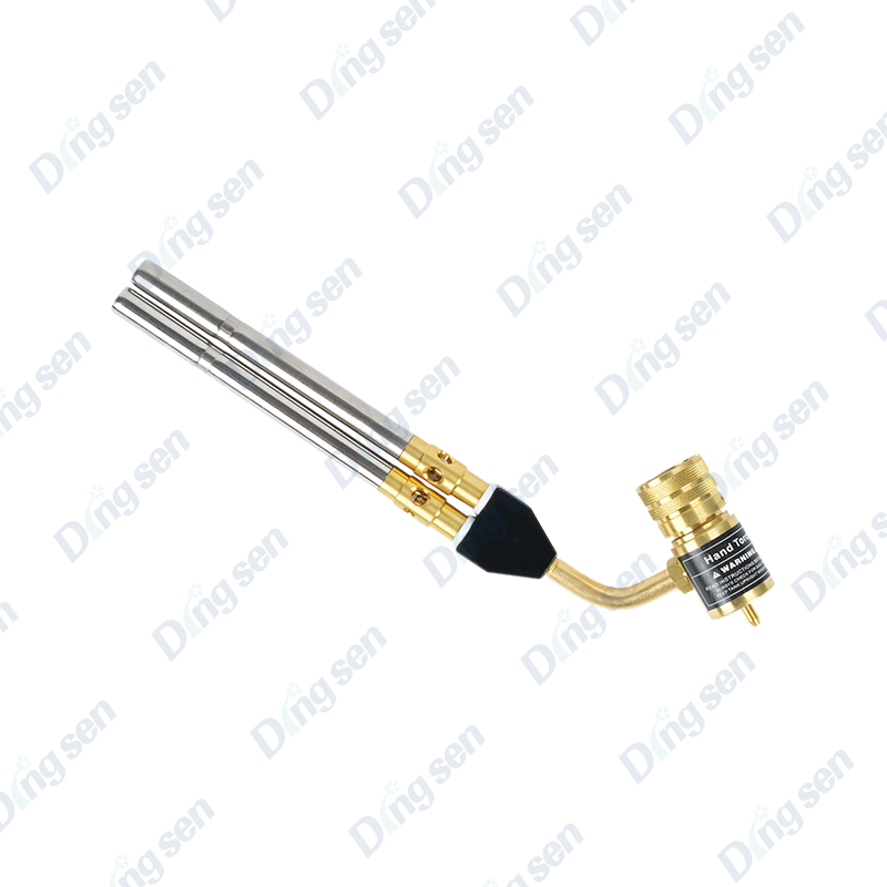 Double tube MAPP welding gunThe dual tube MAPP welding gun is designed for scenarios such as air conditioning and refrigeration system maintenance, precision welding of copper pipes, etc. It adop...View Product →
How Much Energy Are We Really Talking About
Ignition energy of common flammable substances
Figure 1. Minimum ignition energy of common flammable substances, in millijoules
Figure 1 plots the ignition energy of five substances that turn up in refrigeration and process plants. Hydrogen needs only about 0.017 mJ, roughly one sixteenth of the energy that methane requires. That is why the same transmitter can carry a comfortable current margin in a natural gas plant and still fail the entity check on a hydrogen skid, because the gas group changes the curve the calculation runs against. The numbers also explain why the standard works in milliwatts, since a well charged human body can release far more than 0.017 mJ. Practical design therefore aims at milliwatt operation, and that is the arithmetic behind the 1.5 safety factor.
Stored energy in the connecting cable
Figure 2. Stored cable energy against cable length at a 24 V loop voltage
Figure 2 converts cable capacitance into stored energy with the familiar half C V squared relationship at a loop voltage of 24 V. The instrument cable at about 60 pF per metre reaches roughly 8.6 microjoules over 500 m, while the general purpose cable at 200 pF per metre passes 28.8 microjoules over the same distance. The dashed line marks the 0.017 mJ ignition energy of hydrogen, which the general purpose cable crosses at around 300 m and the instrument cable never reaches within the charted range. That crossing is why cable type, cable length and loop voltage belong on the control drawing instead of being left to the installer. It also explains why swapping a cable on site for a higher capacitance equivalent is a design change rather than a maintenance decision.
Two Comparisons That Decide a Design
How much of a barrier rating a loop consumes
Figure 3. Share of each barrier limit used by a 24 V, 20 mA transmitter on a 28 V, 93 mA, 0.65 W barrier
Figure 3 takes a common arrangement, a 24 V transmitter drawing 20 mA from a barrier rated at 28 V, 93 mA and 0.65 W, and shows how much of each limit the loop consumes. Voltage is the tightest constraint at about 86 percent, power follows at roughly 74 percent, and current is barely touched at around 22 percent. That imbalance is normal, because hazardous area loops are almost always voltage limited while the current headroom looks generous. It matters when someone wants to add a second device to the same barrier or lengthen the run, since the voltage budget disappears long before the current budget does. Checking all three pairs, rather than the one that looks comfortable, is what keeps a loop certified.
Protection methods across five practical criteria
Figure 4. Protection methods scored from one to five across five selection criteria
Figure 4 scores intrinsic safety, flameproof protection and non incendive protection from one to five on the criteria that usually decide a project: suitability for Zone 0, tolerance of live maintenance, installed cost, wiring simplicity and weight of hardware. Intrinsic safety fills the shape towards Zone 0 and live maintenance, which is why it is the default for instruments that must be calibrated while the plant is running. Flameproof protection stretches towards wiring simplicity, because the enclosure does the work and no loop calculation is needed, but it scores low on live maintenance and hardware weight. Non incendive protection reaches the outer edge on cost and wiring because it is only intended for Zone 2, where a flammable atmosphere is unlikely and short lived. Reading the three shapes together gives the practical rule: match the method to the zone first, then let cost and maintenance choose between the methods that qualify.
Verification is what separates a compliant installation from one that merely looks convincing. Before a loop goes into service, check the certificate number and the marking on the device, confirm that Uo is at or below Ui, that Io is at or below Ii and that Po is at or below Pi, then add the cable capacitance and inductance against Co and Lo. Read the special conditions printed after the certificate number as well, since they often carry an X and a restriction on how the device may be used. Finally, confirm the temperature class against the gas or vapour actually present, because a device rated for T4 is not automatically acceptable where a T6 limit has been set.
Component selection usually decides how easy that exercise becomes. A pressure switch with published entity parameters, a solenoid coil rated for the zone and a cable whose capacitance is stated on the datasheet turn a difficult calculation into a short checklist. When a project mixes flammable refrigerant circuits with classified areas, it is worth reviewing the component list against the loop calculation early, before the drawings are fixed.
If you are specifying parts for a system like this, talk to our engineering team about the refrigerant, the zone and the control voltage before the order is placed.
-
The Safety filling valve series is a safety control component during media filli...
-
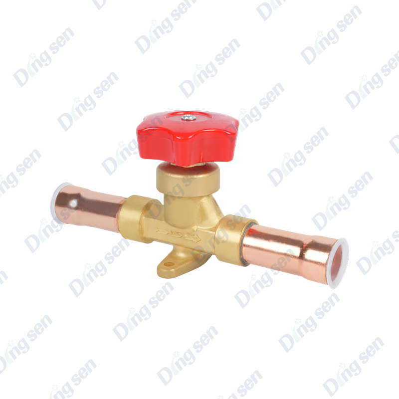
Diaphragm-type hand valves are manual flow control components for refrigeration ...
-
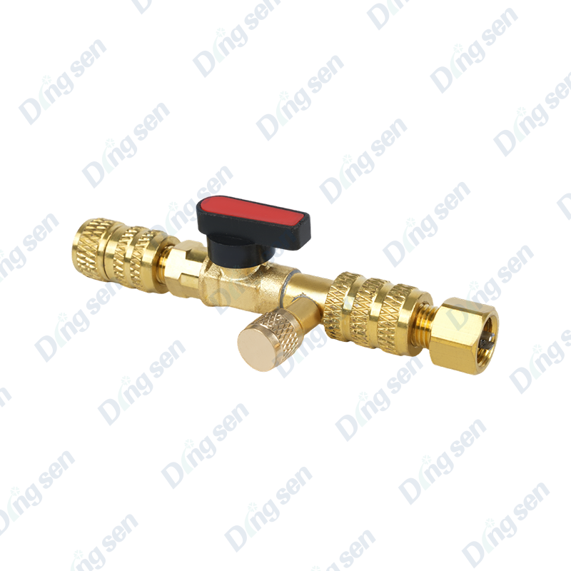
Valve core installation and removal tools are specialized tools for installing a...
-
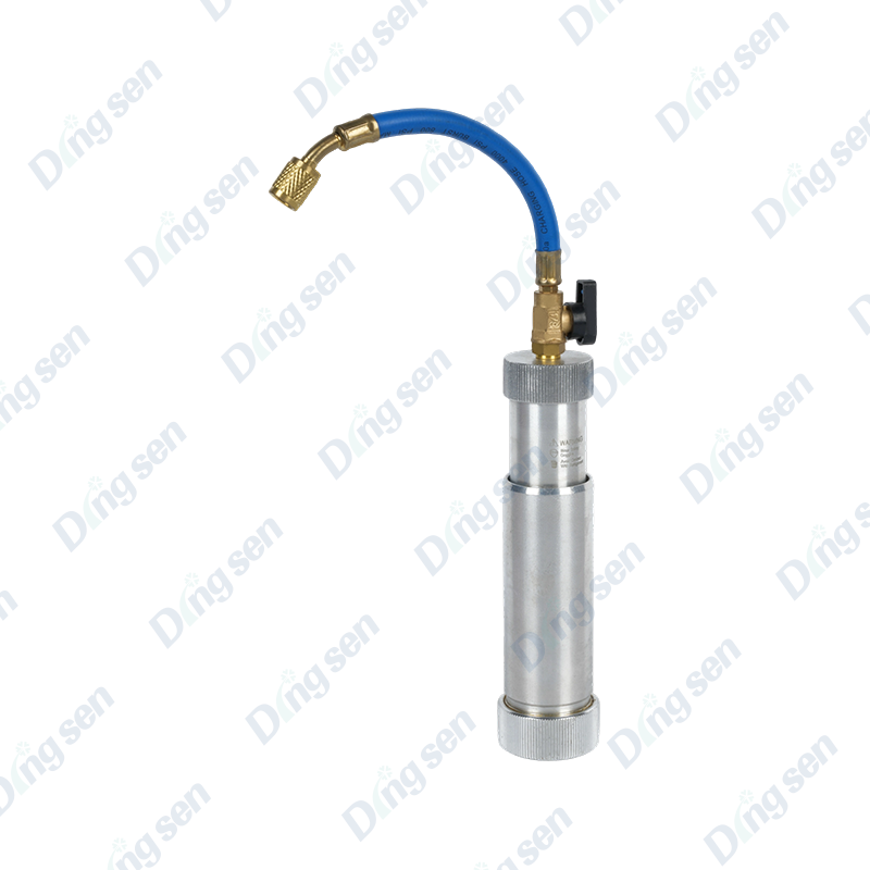
Refrigerant and refrigeration oil filler is a special device for replenishing me...
-
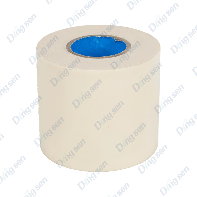
Air conditioning pipe bandage strip is used to secure and protect the pipes conn...
-
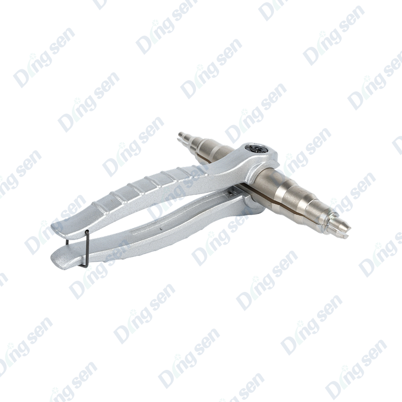
The copper tube expander is a specialized tool for copper tube connection. It ex...

Contact Us
-

No. 109 Jiefang Road, Diankou Town, Zhuji City, Shaoxing, Zhejiang Province
-

+86-13867581196
-

Copyright © shaoxing DingSen Refrigeration Technology Co Ltd. All Rights Reserved
OEM Refrigeration Parts Manufacturer Custom Automotive AC Parts Factory